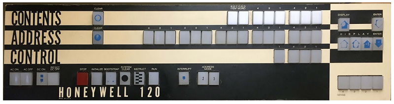
The first computer I learned to program was a Honeywell Model 120 at the School of Computer Technology, a tech school in the Fulton Building, downtown Pittsburgh.
Honeywell, looking at the success of IBM 1401, developed a small business computer named H-200 and announced it December 3rd 1963. The series 200 was about 5x faster than the IBM 1401 and was offered at a lower price. It attacks frontally the IBM 1401 through a program named Liberator the main feature of it was a Translator for assembly language of 1401.
Several models were introduced between 1963 and 1974:
The line was discontinued in the early 1970s.
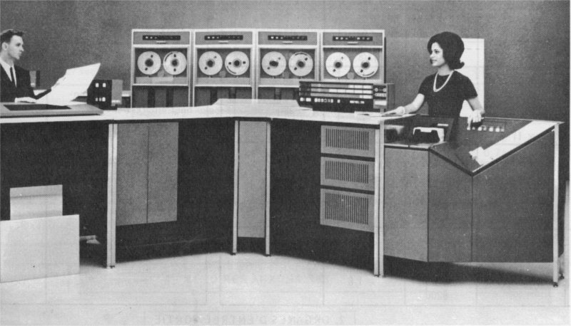
The 120 computer was introduced in 1965 and was the smallest of the series at the time. The 120 had integrated controllers for a card reader, a card punch, and a 450 LPM line printer, and could be equipped with as little as 2K characters of 3-microsecond core memory or as much as 32K characters. The 2K processor cost $37,155 [$352.825 adjusted for inflation, 220910] and the 32K processor cost $109,515 in 1965 [$1,039.957 adjusted for inflation]. The 120 did not have hardware instructions for multiply or divide, or any floating point instructions. An add on controller supported 4x magnetic tape drives. The line was discontinued in the early 1970s.
The H200 memory consisted of individually-addressed characters, each composed of six data bits, two punctuation bits and a parity bit. The two punctuation bits recorded a word mark and an item mark, while both being set constituted a record mark. The item bit permitted item moves and record moves in addition to word moves (move successive characters one-by-one starting at the addresses given in the instruction, stopping when the relevant punctuation mark was found set in either field).
An instruction consisted of a one-character op-code, and up to two operand addresses. Usually the op-code character would be word-marked, confirming the end of the previous instruction. An item-marked op-code would be handled differently from normal, and this was used in the emulation of IBM 1401 instructions that were not directly compatible. The first three bits of an operand address could designate one of eight index registers that occupied the first 32 addressable memory locations.
A Change Address Mode (CAM) instruction switched between 2-, 3- and 4-character address modes. The address mode specified the number of characters needed for each operand address in instructions.
A Change Sequence Mode (CSM) instruction stored the next instruction address in a memory location and loaded the instruction counter from another memory location.
While the H200 supported operation with just a console, card reader and punch like the IBM 1401, the generic Input-Output instuctions also supported line printers and magnetic tape drives.
IO instructions left punctuation bits unchanged, reading or writing only data (and parity) bits into memory, and terminating on any record mark encountered. A record mark could be placed at the end of an input buffer to prevent any buffer overflow, a problem that was to persist in many other systems into the 21st century.
The 200-series IO instructions were a Peripheral Data Transfer (PDT) and a Peripheral Control and Branch (PCB) that explicitly implemented asynchronous IO. The PDT specified a device address, a buffer address and the transfer operation to be started, while the PCB specified a device address, and set the operating mode or tested the status of the device.
The native assembly language was named Easycoder. The Easycoder assembler generated an object file as a binary card deck that could be punched to cards or written to magnetic tape instead. The object file began with a bootstrapping routine so that each program could be loaded into memory, from card reader or magnetic tape, using a boot command from the console.